Skewed-Joint Welding Symbol
A skewed-joint callout applies where members meet at an angle that makes the usual symmetric joint picture misleading.
- Use the actual member angle instead of a ninety-degree assumption
- Carry arrow-side logic through rotated views
- Verify how weld size and root are defined for the skewed geometry
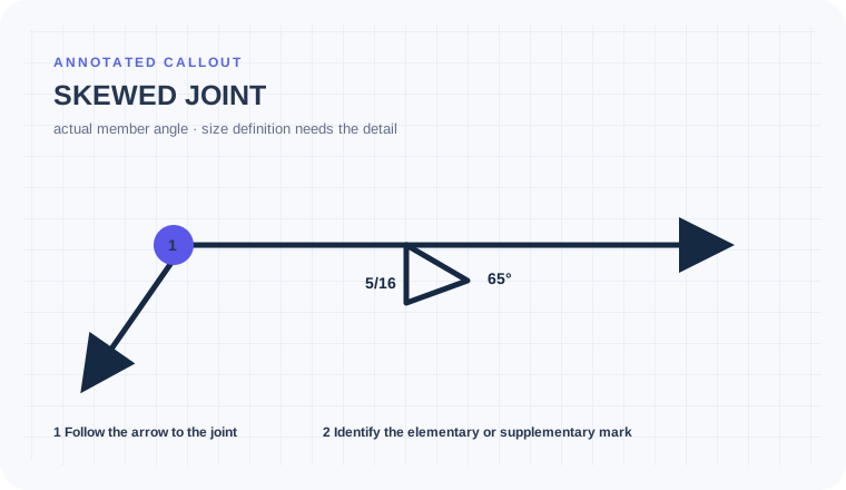
Forcing a ninety-degree mental model
A standard-looking fillet or groove symbol can map to unusual physical geometry. If the reader imagines a square tee joint, the prepared member, root, size, access, and inspection location may all be wrong.
A diagonal brace meets a plate at sixty degrees
The elevation makes the joint look ordinary, but the section view shows a 60-degree intersection and limited torch access on one side.
Use the section to locate the actual root and member faces, assign side from the arrowed joint, then read the weld size and extent under the stated skewed-joint convention.
The weld is assigned to the correct physical surface and checked for achievable access instead of being laid out as a ninety-degree fillet.
Use the actual member angle instead of forcing a square tee joint.
A diagonal brace meets a plate at 65 degrees. Familiar fillet conventions must be checked against the real root, legs, access, and measurement method.
Do not rotate the joint mentally back to ninety degrees.
Keep arrow-side logic tied to the physical surfaces despite the skew.
Confirm how weld size and acceptance are defined for the actual angle.
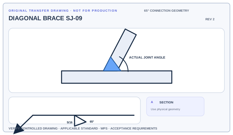
Mark the actual root and both member surfaces, identify which conventional fillet assumptions no longer hold automatically, and write the clarification needed for weld size.
Deliverable · A skew-joint clarification that identifies the geometry used to measure sizeCompare with the field read +
The brace-to-plate joint remains governed by the arrow and symbol placement, but its 65-degree geometry changes how the weld fits and may change how size is specified or measured. The detail and procedure must settle that point.
Read the symbol against a non-right-angle joint
Begin with the cue in the first column. The final column records the drawing, detail, procedure, or acceptance question that this callout cannot answer by itself.
| Visual cue | What it establishes | What still needs verification |
|---|---|---|
| Section/detail angle | Actual member geometry at the joint | Do not derive the angle from the projected elevation alone. |
| Arrow and symbol placement | Applicable physical side of the skewed joint | Rotation of the view does not change side significance. |
| Size definition | Required weld geometry under the governing detail/convention | Do not assume familiar equal legs or throat at a non-right angle. |
| Access and extent | Where the weld can be deposited and how far it runs | Check interference, start/stop location, and WPS limits. |
Map root, legs, and side on the actual geometry
Use the section or detail view to identify the actual member angle and accessible weld side. Read weld size and groove or contour information against the real joint geometry, not a mental ninety-degree joint.
- Use the section or detail view to identify the actual member angle and accessible weld side.
- Read weld size and groove or contour information against the real joint geometry, not a mental ninety-degree joint.
- A skewed joint changes physical geometry; it does not change arrow-side logic or make an unspecified dimension automatic.
- Verify member angle, root location, weld-size definition, access, fit-up detail, design intent, and WPS.
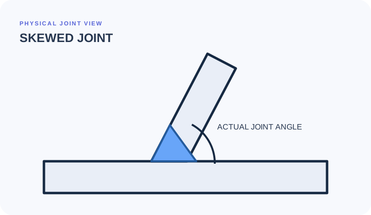
Skew changes geometry without changing arrow-side logic
Skewed joint
Members meet at a nonstandard angle
Evidence to useWhat does the section view show?Square tee joint
Members meet approximately at ninety degrees
Evidence to useAre equal-leg assumptions actually supported?Rotated view
Only the page presentation changes
Evidence to useDoes the physical joint remain the same?Ninety-degree habits carried into a 65-degree connection
Forcing a ninety-degree mental model
Leg dimensions and root location must be interpreted against the real member angle, not an assumed square tee joint.
Using page direction as side
Rotation of the view does not change arrow-side logic. Trace the arrow to the physical joint and surfaces.
Ignoring access and size definition
A familiar fillet mark does not prove that the illustrated size can be deposited or measured conventionally at the skew angle.
Is weld size measurable on the joint that is actually drawn?
Use the full list before fabrication, fit-up, or inspection. This is a drawing-reading handoff—not a substitute for the governing acceptance standard.
- 01Find the true section/detail
- 02Identify member angle and root
- 03Assign arrow side physically
- 04Read the stated weld-size definition and extent
- 05Verify fit-up, access, inspection, and WPS
Evidence and limits for this Skewed Joint lesson
This guide teaches common AWS-style drawing interpretation. It is educational material, not a substitute for the purchased standard, project specification, code, WPS, or qualified engineering direction.
How this page was made. The training diagrams, worked example, comparisons, and questions are original educational material. Read the editorial and technical review policy for the full process.
Save your place after Skewed Joint.
This marker records reading progress only; it does not mean the topic is mastered. Use the six-question practice page to check your understanding.
Build outward from Skewed Joint
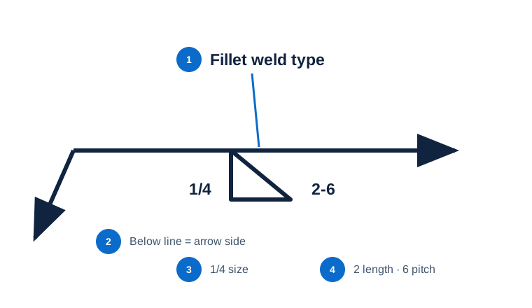 Fillet Weld
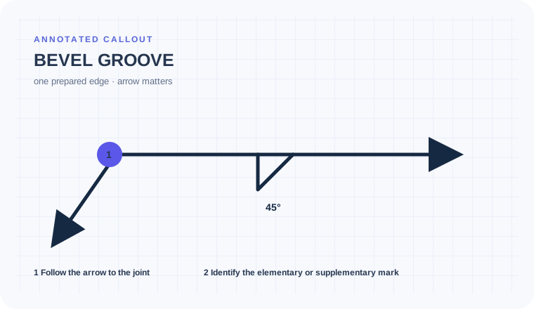 Bevel Groove
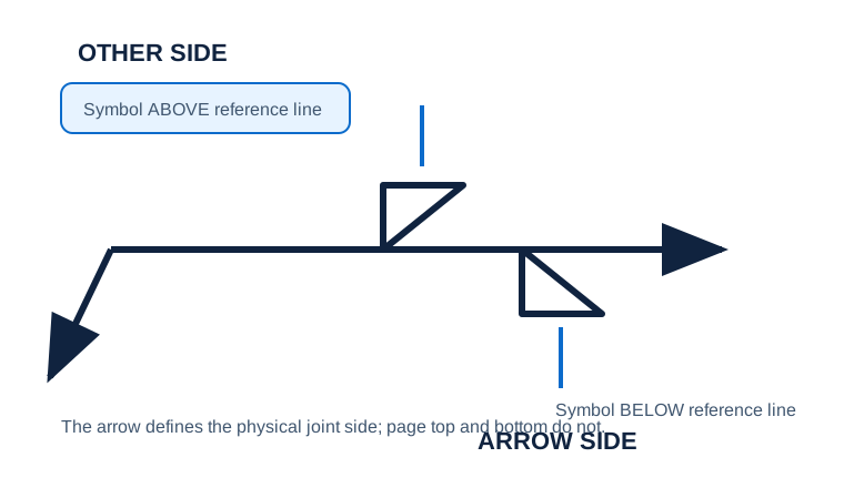 Arrow Side vs Other Side
Educational practice only. Verify production work against the governing drawing, applicable standard, WPS, and qualified instruction.