Combination Groove Weld Symbols
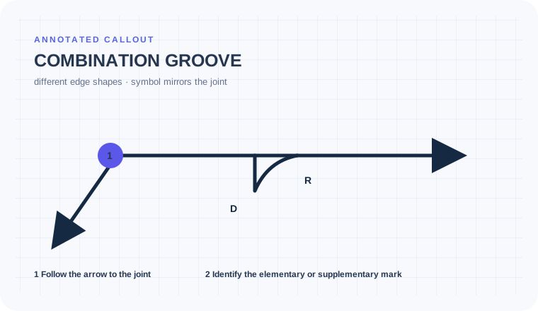
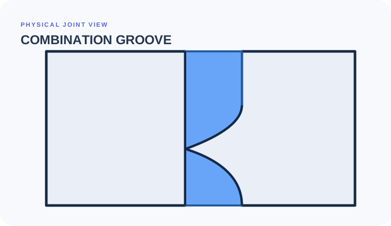
A combination groove uses different edge shapes together so the welding symbol reflects the actual asymmetric joint configuration.
- Match two different edge shapes to their members
- Interpret groove-element orientation with the actual joint
- Keep dimensions attached to the correct preparation element
Collapsing two shapes into one family
Combination grooves exist because one familiar groove family cannot describe the joint. Simplifying the symbol into a V, bevel, or flare can send the wrong member to machining and change root geometry or weld volume.
A rolled edge meets a machined bevel
DETAIL B shows a curved formed member against a straight prepared plate, with the combination symbol oriented to match that physical configuration.
Trace the arrow to DETAIL B, match the flare element to the rolled member and the bevel element to the machined plate, then assign each angle, depth, and opening by position.
Only the intended plate is machined, the formed radius is preserved, and dimensions are not borrowed across the two groove elements.
Map each symbol element to its own member.
A transition joint combines one straight preparation with one curved preparation. Treating the mark as a single familiar groove loses the member-specific geometry.
Name both edge forms before naming the combined joint.
Use symbol orientation and the physical detail together; page reversal does not change side.
Do not borrow one dimension for both preparation elements.
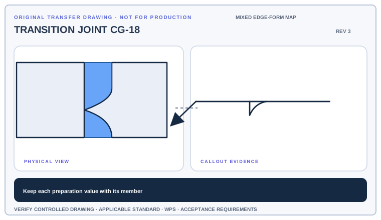
Color-code each symbol element and the member it controls, then create separate preparation notes for angle, depth, root opening, and radius where applicable.
Deliverable · A two-member preparation map with no shared dimensions unless the drawing supports themCompare with the field read +
One member receives the straight preparation and the other receives the curved preparation shown in the combination. Each angle, depth, opening, or radius stays with the element established by placement and detail.
A combination groove is not a distorted V, bevel, U, or J
Combination groove
Two different edge shapes share one joint
Evidence to useCan you name each member's preparation?V or U groove
Matching preparation family on both members
Evidence to useAre the two edge shapes actually symmetric?Single bevel or J
One prepared member meets an unprepared mate
Evidence to useDoes the second member contribute a different formed shape?Split the combined mark into member-specific elements
Begin with the cue in the first column. The final column records the drawing, detail, procedure, or acceptance question that this callout cannot answer by itself.
| Visual cue | What it establishes | What still needs verification |
|---|---|---|
| Joint section | Shows which member is curved, square, beveled, or otherwise prepared | Name each edge shape before reading dimensions. |
| Two combined groove elements | Different edge shapes act together at one joint | Do not collapse them into one symmetric family. |
| Element orientation | Can depict the actual configuration under the AWS A2.4:2020 convention | Use the arrow and detail; reversed drawing does not automatically mean other side. |
| Local dimensions | Control the corresponding preparation element | Associate angle, depth, opening, and size individually. |
Write two preparation notes for one joint
Match each side of the groove symbol to the corresponding member shape in the joint detail. Read each groove element's orientation, then assign depth, size, angle, root opening, and contour to the correct preparation.
- Match each side of the groove symbol to the corresponding member shape in the joint detail.
- Read each groove element's orientation, then assign depth, size, angle, root opening, and contour to the correct preparation.
- A combination groove communicates two different edge shapes; a V, U, or square groove uses one matching groove family.
- Verify member profiles, symbol orientation, preparation dimensions, root condition, reference-line use, access, and WPS.
Dimensions that cross from one edge form to the other
Collapsing two shapes into one family
A combination groove intentionally communicates different edge forms. Naming only V, bevel, or flare loses one member's preparation.
Treating reversed drawing as other side
A groove element may be drawn backward to depict actual joint configuration; orientation must be read with the arrow and detail.
Borrowing one dimension for both elements
Angle, depth, root opening, and preparation can belong to different parts of the combined joint. Associate every value by placement.
Can each preparation value be traced to one member?
Use the full list before fabrication, fit-up, or inspection. This is a drawing-reading handoff—not a substitute for the governing acceptance standard.
- 01Open the referenced section/detail
- 02Name each member edge shape
- 03Match each symbol element to its member
- 04Assign every dimension by position
- 05Verify root fit, machining, access, and WPS
Evidence and limits for this Combination Groove lesson
This guide teaches common AWS-style drawing interpretation. It is educational material, not a substitute for the purchased standard, project specification, code, WPS, or qualified engineering direction.
How this page was made. The training diagrams, worked example, comparisons, and questions are original educational material. Read the editorial and technical review policy for the full process.
Save your place after Combination Groove.
This marker records reading progress only; it does not mean the topic is mastered. Use the six-question practice page to check your understanding.
Build outward from Combination Groove
 Groove Welds Overview
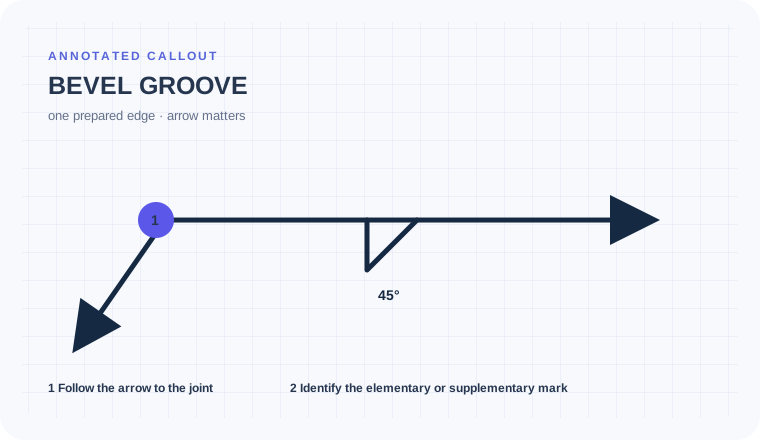 Bevel Groove
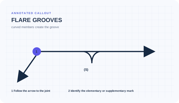 Flare Grooves
Educational practice only. Verify production work against the governing drawing, applicable standard, WPS, and qualified instruction.