Groove Weld Symbols
Groove weld symbols identify the joint preparation or groove form used for a groove weld. Common forms include square, V, bevel, U, J, and flare grooves; the complete callout can also specify depth, groove angle, root opening, and other requirements.
- Classify square, V, bevel, U, J, and flare groove families
- Separate root opening, groove angle, and depth
- Use the arrow and joint detail to assign asymmetric preparation
Angle confusion
Groove symbols describe joint preparation as well as welding. Confusing angle, gap, and prepared member can make parts impossible to fit before welding begins.
One prepared edge, two prepared edges, or natural curvature?
V / U groove
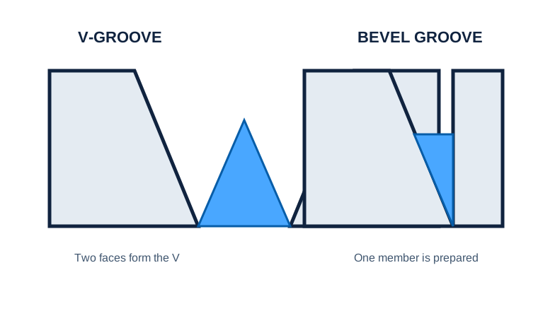
Preparation is generally symmetric across the joint
Evidence to useAre both members prepared? Confirm the detail.Bevel / J groove
Preparation is asymmetric
Evidence to useUse arrow convention and the detail to identify the prepared member.Flare groove
Member curvature creates the groove
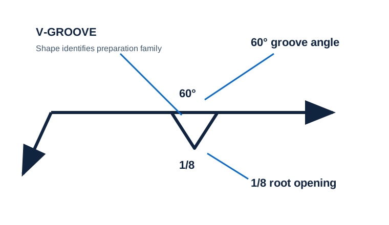
Evidence to useDo not invent machined edge preparation.A V-shaped callout includes 60° and 1/8
The print shows an included angle and a value inside the groove symbol.
Treat 60° as the included groove angle and 1/8 as the illustrated root opening; then find any depth, size, backing, or detail reference elsewhere in the callout.
The joint is not fabricated from the V shape alone, and root opening is not mistaken for weld size.
Read shape as a preparation family
Begin with the cue in the first column. The final column records the drawing, detail, procedure, or acceptance question that this callout cannot answer by itself.
| Visual cue | What it establishes | What still needs verification |
|---|---|---|
| Groove shape | The preparation family: square, V, bevel, U, J, or flare | Match it to the physical joint detail, not just a memorized icon. |
| Degree value | Groove or bevel angle according to its placement | Included groove angle and one member’s bevel angle are not automatically equal. |
| Value inside the symbol | Root opening in the illustrated convention | It is the separation at the root before welding, not penetration. |
| Value to the left | Depth/size information as defined by the complete notation | Parentheses and project convention can change what is being specified. |
Choose the preparation before estimating weld volume.
A splice schedule offers square, V, bevel, U, J, and flare families. The decision depends on member preparation and natural joint geometry—not which icon looks closest.
Separate naturally curved member geometry from machined preparation.
Do not halve an included angle unless the joint detail actually shows symmetric bevels.
For bevel and J preparations, confirm which member the arrow convention selects.
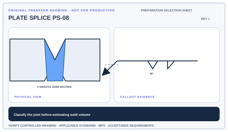
For each of three joint thumbnails, name the groove family, identify the prepared member or members, and list the next dimension needed before fabrication.
Deliverable · A three-row preparation schedule with one unresolved requirement per jointCompare with the field read +
Classify the physical joint first, then attach angle, root opening, depth, and backing information to that family. A groove icon alone is not enough to release edge preparation.
Build the joint-prep decision in the right order
Identify the groove shape first, then separate preparation dimensions from weld dimensions. For bevel- and J-groove applications, use the arrow and drawing detail to establish which member is prepared.
- Identify the groove family from the elementary symbol.
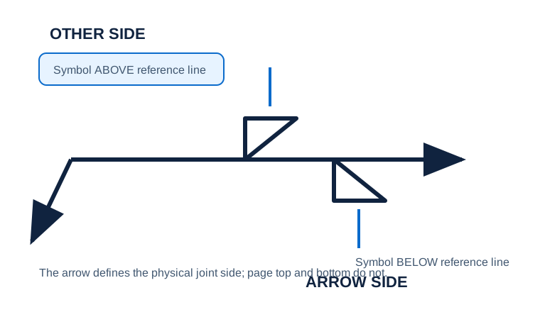
- Determine arrow-side or other-side placement.
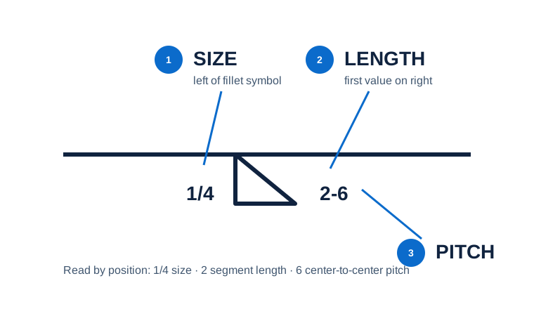
- Read depth or size to the left and root opening inside the symbol when shown.
- Read groove angle and check the drawing detail for member preparation and joint geometry.
Prep assumptions that reach the shop before the drawing does
Angle confusion
Groove angle describes the included angle between groove faces; a bevel angle can describe a single prepared face.
Wrong member preparation
For asymmetric preparations, the arrow and joint detail matter. Do not select a member by visual guesswork.
Mixing the root gap with depth
Root opening is the separation at the joint root before welding; it is not groove depth or effective throat.
Is the joint fabricable from the information shown?
Use the full list before fabrication, fit-up, or inspection. This is a drawing-reading handoff—not a substitute for the governing acceptance standard.
- 01Name the groove family
- 02Assign side and prepared member
- 03Separate angle, root opening, and depth
- 04Find backing/root requirements
- 05Confirm the joint detail and WPS
Evidence and limits for this Groove Welds Overview lesson
This guide teaches common AWS-style drawing interpretation. It is educational material, not a substitute for the purchased standard, project specification, code, WPS, or qualified engineering direction.
How this page was made. The training diagrams, worked example, comparisons, and questions are original educational material. Read the editorial and technical review policy for the full process.
Save your place after Groove Welds Overview.
This marker records reading progress only; it does not mean the topic is mastered. Use the six-question practice page to check your understanding.
Build outward from Groove Welds Overview
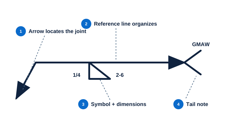 Symbol Anatomy
 Arrow Side vs Other Side
 Size, Length & Pitch
Educational practice only. Verify production work against the governing drawing, applicable standard, WPS, and qualified instruction.