Flare-V and Flare-Bevel Groove Symbols
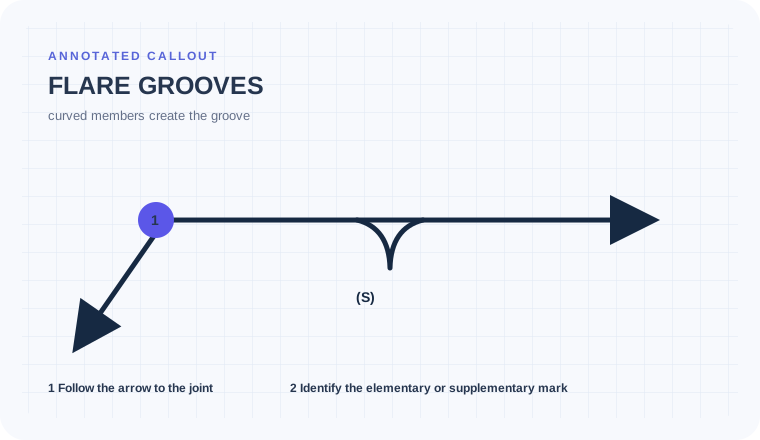
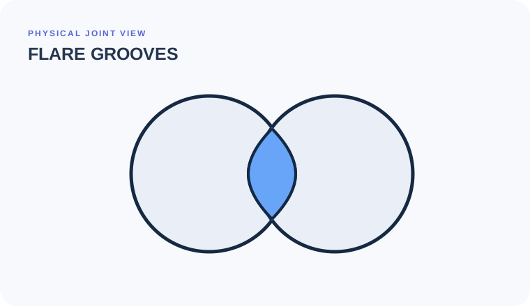
Flare grooves are formed by curved member surfaces rather than machined bevels. A flare-V occurs between two curved members; a flare-bevel occurs between a curved member and a flat member.
- Identify flare-V and flare-bevel joint geometry
- Recognize when member curvature—not machining—creates the groove
- Find the specified weld size/depth instead of assuming the full flare is filled
Calling it a V groove
Flare grooves are common where round bars, tubes, or formed edges meet. Their apparent groove is created by geometry, so conventional V/bevel assumptions can overstate preparation and weld size.
Tube-to-tube and tube-to-plate create different flare families
Flare V
Two curved member surfaces form the groove
Evidence to useAre both sides of the groove naturally curved?Flare bevel
One curved surface meets a flat surface
Evidence to useIs only one side naturally curved?Machined V/bevel
Prepared straight faces create the groove
Evidence to useDoes the detail call for edge preparation?A round tube meets a flat plate
The curved tube surface creates a groove along the contact line without edge machining.
Classify the joint as flare-bevel geometry, then read required size/depth, length, side, and any detail defining effective throat or extent.
The crew preserves the formed member and does not machine an unnecessary bevel.
Let member curvature create the groove.
A tube frame includes tube-to-tube and tube-to-plate connections. Both create flare geometry without machining a conventional bevel.
Two curved surfaces create the flare-V condition.
One curved and one flat surface create the flare-bevel condition.
Do not assume the member radius establishes required penetration or weld size.
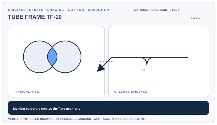
Classify one flare-V and one flare-bevel location, identify the curved and flat surfaces, and list the weld-size evidence still required.
Deliverable · A two-joint geometry comparison tied to actual member surfacesCompare with the field read +
The tube-to-tube joint is flare-V; the tube-to-plate joint is flare-bevel. Natural member curvature identifies the family, while size and acceptance require the complete callout and governing requirements.
Match the flare mark to member curvature
Begin with the cue in the first column. The final column records the drawing, detail, procedure, or acceptance question that this callout cannot answer by itself.
| Visual cue | What it establishes | What still needs verification |
|---|---|---|
| Two opposing curved forms | Flare-V groove geometry | Confirm the members’ actual radii and contact condition. |
| One curved and one flat form | Flare-bevel groove geometry | Do not read it as a straight machined bevel. |
| Size/depth value | Controls the weld requirement as defined by the callout | Do not assume the entire visible flare volume must be filled. |
Classify the physical joint before reading size
Use the joint geometry to distinguish two curved members from one curved and one flat member, then read any depth of groove and groove weld size values to the left.
- Inspect whether the joint has two curved surfaces or one curved and one flat surface.
- Match that geometry to flare-V or flare-bevel.
- Determine side significance from the reference line.
- Read groove depth, weld size, length, and applicable detail requirements.
Machined-groove assumptions that ignore natural radius
Calling it a V groove
A flare-V comes from two curved surfaces; it is not necessarily a V preparation machined into both edges.
Ignoring member geometry
The elementary symbol must be matched to the physical round-to-round or round-to-flat joint.
Assuming full radius penetration
Required groove weld size and acceptance come from the complete callout and governing requirements.
Has required weld size been established beyond the member radius?
Use the full list before fabrication, fit-up, or inspection. This is a drawing-reading handoff—not a substitute for the governing acceptance standard.
- 01Inspect actual member geometry
- 02Classify flare V/bevel
- 03Read size/depth and length
- 04Check side and extent
- 05Confirm effective-throat rules and WPS
Evidence and limits for this Flare Grooves lesson
This guide teaches common AWS-style drawing interpretation. It is educational material, not a substitute for the purchased standard, project specification, code, WPS, or qualified engineering direction.
How this page was made. The training diagrams, worked example, comparisons, and questions are original educational material. Read the editorial and technical review policy for the full process.
Save your place after Flare Grooves.
This marker records reading progress only; it does not mean the topic is mastered. Use the six-question practice page to check your understanding.
Build outward from Flare Grooves
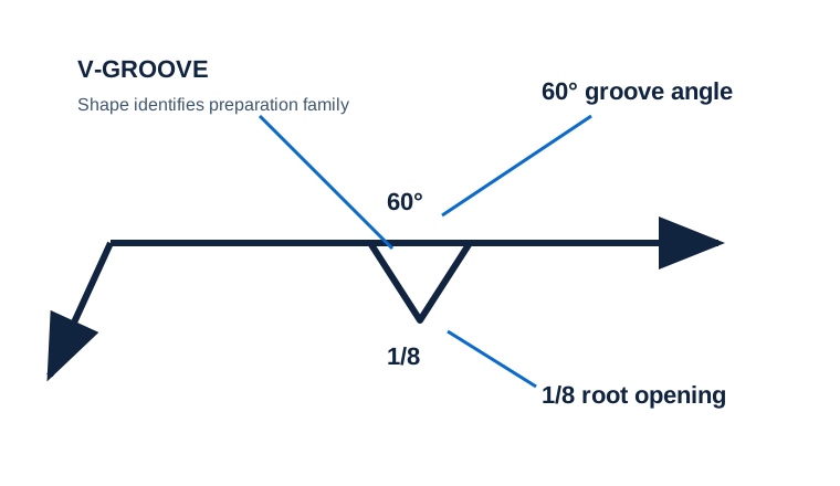 Groove Welds Overview
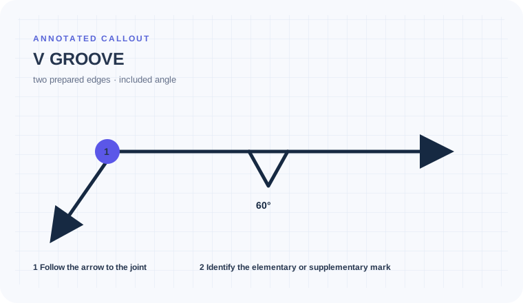 V Groove
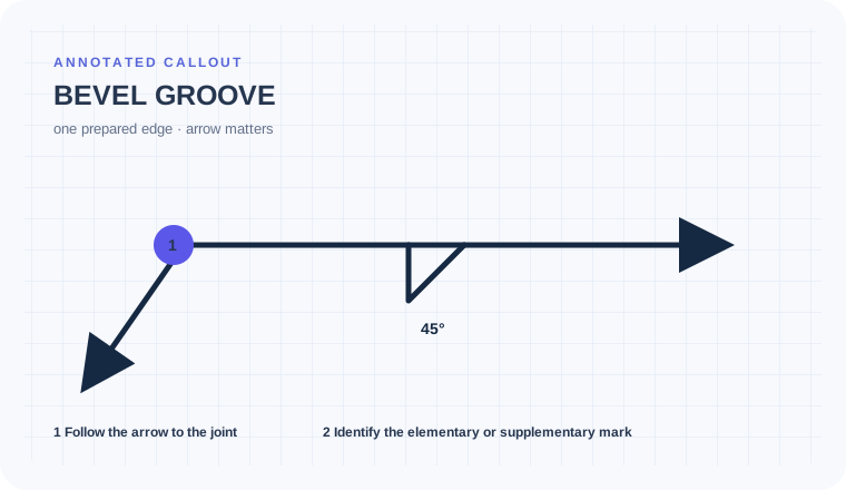 Bevel Groove
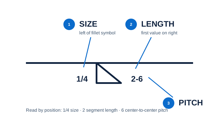 Size, Length & Pitch
Educational practice only. Verify production work against the governing drawing, applicable standard, WPS, and qualified instruction.