Edge Weld Symbol
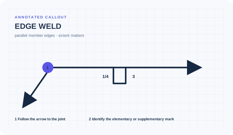
An edge weld joins or builds up the edges of two or more parallel or nearly parallel members. It is distinct from a square-groove weld even when the joint appears similar in a simplified view.
- Recognize an edge-weld instruction on parallel or nearly parallel members
- Distinguish edge weld from square groove and seam weld
- Verify required length and edge preparation from the joint detail
Square-groove substitution
Simplified views can make edge and square-groove configurations look alike. The physical arrangement of the members determines which instruction is plausible.
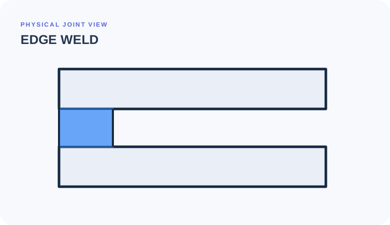
Two sheet edges lie beside one another
The drawing shows parallel members with their edges available for welding.
Use the joint detail to confirm an edge-weld configuration, then read required size, length, side, and any contour or preparation note.
The instruction is not converted into a butt-joint square groove or a resistance seam operation.
Edge weld, square groove, and seam are not visual synonyms
Edge weld
Acts at adjacent member edges
Evidence to useAre the members parallel or nearly parallel?Square groove
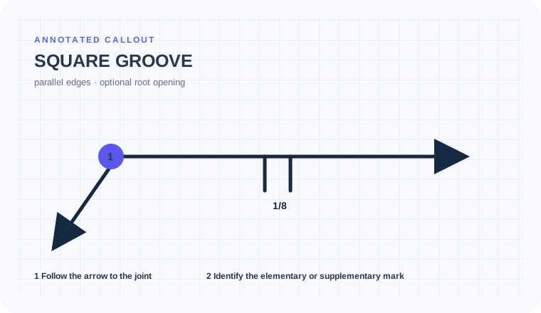
Acts in a butt-type groove between square mating edges
Evidence to useDoes the detail show a groove/root between members?Seam weld
An elongated spot/seam process instruction
Evidence to useLook for the seam elementary symbol and process context.Confirm the member arrangement before calling an edge weld.
Two nearly parallel sheet edges form a closure beside a separate butt joint. The visible outline alone does not establish weld family.
Confirm that the participating members are parallel or nearly parallel in the applicable configuration.
Read size and length from the callout rather than the apparent sheet overlap.
Do not extend the weld along every visible sheet edge.
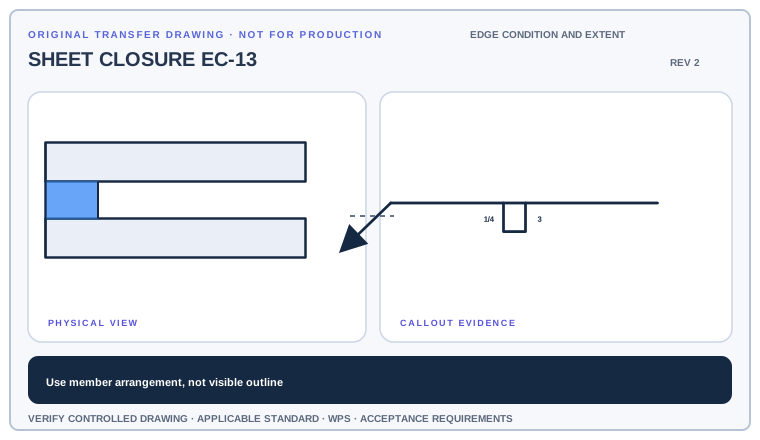
Identify which members create the edge-weld condition, mark its controlled length, and explain why the nearby butt joint needs a different symbol.
Deliverable · A joint-classification markup with edge-weld extentCompare with the field read +
The specified parallel member edges receive the edge weld for the stated extent. The adjacent butt joint is a separate condition and cannot inherit the edge-weld instruction.
Use member arrangement to identify the edge weld
Begin with the cue in the first column. The final column records the drawing, detail, procedure, or acceptance question that this callout cannot answer by itself.
| Visual cue | What it establishes | What still needs verification |
|---|---|---|
| Edge-weld elementary symbol | Welding at edges of parallel or nearly parallel members | Confirm member orientation in section/detail view. |
| Length or extent | Controls how much of the edge is welded | A visible edge is not automatically welded full length. |
| Contour/finish modifier | Controls finished edge-weld profile | It does not change the underlying joint family. |
Tie size and extent to the participating edges
Confirm that the weld is applied at member edges rather than deposited in a butt-joint groove, then read weld size, length, pitch, and extent from the complete callout.
- Locate the member edges identified by the arrow.
- Distinguish an edge weld from a square-groove or seam weld.
- Read size to the left and length or pitch to the right when shown.
- Check the detail for member count, edge preparation, and weld extent.
Outline-reading shortcuts that select the wrong joint family
Square-groove substitution
A groove weld is deposited in a joint groove; an edge weld applies to edges of parallel or nearly parallel members.
Missing member count
The detail must make clear which edges and how many members are included.
Assuming full length
Read explicit length, pitch, and extent rather than using the entire visible edge automatically.
Are the participating edges and weld limits explicit?
Use the full list before fabrication, fit-up, or inspection. This is a drawing-reading handoff—not a substitute for the governing acceptance standard.
- 01Confirm member arrangement
- 02Identify the applicable edges
- 03Read size and length
- 04Check contour/preparation
- 05Verify access and drawing detail
Evidence and limits for this Edge Weld lesson
This guide teaches common AWS-style drawing interpretation. It is educational material, not a substitute for the purchased standard, project specification, code, WPS, or qualified engineering direction.
How this page was made. The training diagrams, worked example, comparisons, and questions are original educational material. Read the editorial and technical review policy for the full process.
Save your place after Edge Weld.
This marker records reading progress only; it does not mean the topic is mastered. Use the six-question practice page to check your understanding.
Build outward from Edge Weld
 Square Groove
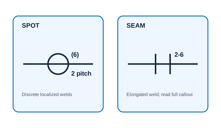 Spot & Seam Welds
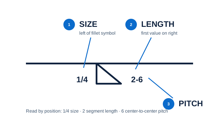 Size, Length & Pitch
Educational practice only. Verify production work against the governing drawing, applicable standard, WPS, and qualified instruction.