J-Groove Weld Symbol
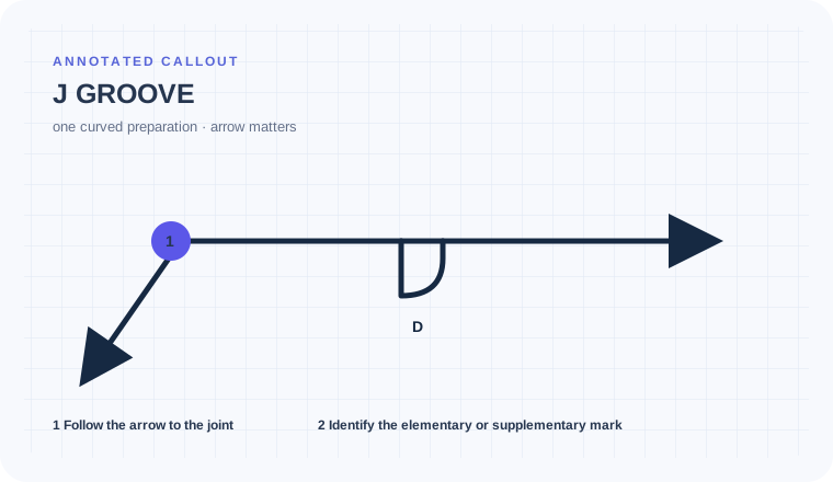
A J-groove weld uses concave preparation on one member while the mating member remains square. It is the asymmetric counterpart of the U groove.
- Recognize curved preparation on one member
- Assign the prepared member correctly
- Distinguish J groove from U, bevel, and flare-bevel joints
Preparing both edges
J grooves combine asymmetric preparation with a controlled curved profile. Both the correct member and the exact geometry matter before welding starts.
Only one thick member receives curved preparation
A J-groove callout points to a joint between a heavy member and a square mating face.
Use the arrow and detail to assign the prepared member, then locate radius, depth, root face/opening, and any backing requirement.
The shop does not curve both members into a U groove or mistake natural member radius for a machined J.
Put the curved preparation on the specified member only.
A nozzle ring joins a square mating member. One edge receives a curved J preparation; the other does not.
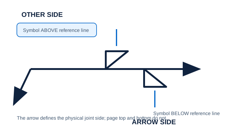
Use arrow convention and section geometry to assign the curved preparation.
Keep the second member square unless the drawing adds another preparation.
Do not infer preparation radius from the drawn J icon.
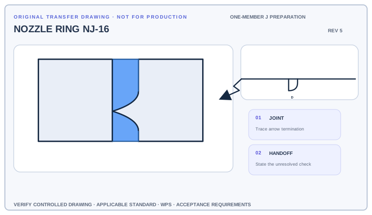
Identify the prepared member in the section, list radius/depth/root requirements still missing, and write a note that prevents the shop from cutting a U groove.
Deliverable · A one-member machining note with an explicit square mating edgeCompare with the field read +
The selected member receives the controlled curved J preparation and the mating edge remains square in this detail. Radius, depth, opening, and acceptance come from the supporting detail and WPS.
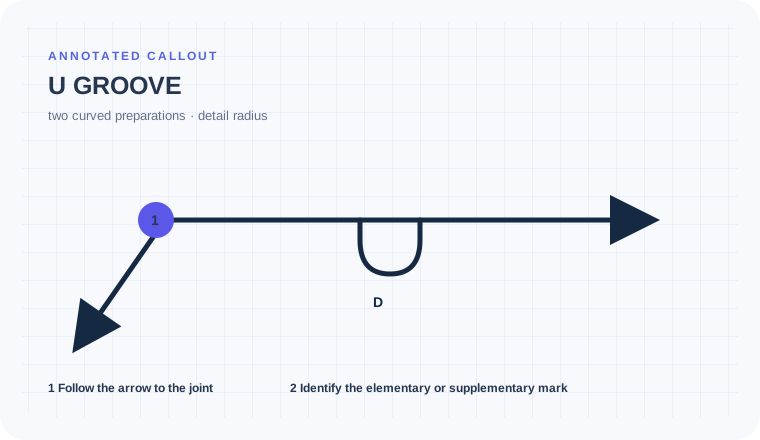
J versus U: one curved edge or two
J groove
One curved prepared face
Evidence to useWhich member is prepared?U groove
Two curved prepared faces
Evidence to useIs preparation symmetric?Flare bevel
Natural member curvature creates the groove
Evidence to useIs machining actually called for?Read the J as asymmetric preparation
Begin with the cue in the first column. The final column records the drawing, detail, procedure, or acceptance question that this callout cannot answer by itself.
| Visual cue | What it establishes | What still needs verification |
|---|---|---|
| J-shaped elementary symbol | Curved preparation on one mating member | The opposite member normally remains square in the illustrated joint family. |
| Arrow convention/detail | Assigns the prepared member | Do not choose by page position or material thickness alone. |
| Radius/depth information | Defines the actual prepared profile | The symbol’s curve is not to scale. |
Describe the prepared and unprepared members
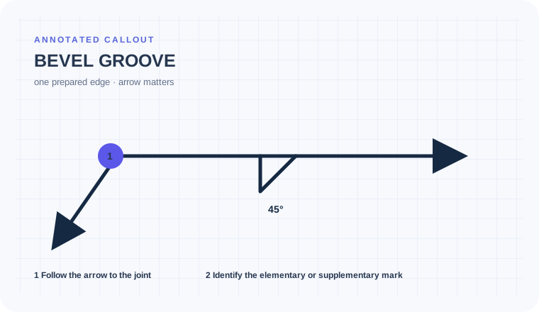
Identify the vertical-and-curved J symbol, then use the arrow and joint detail to assign the prepared member before reading depth, size, angle, and root opening.
- Distinguish the J groove from the symmetric U groove.
- Follow the arrow to the joint and identify the prepared member.
- Read depth, weld size, and root opening by position.
- Verify radius and root-face geometry in the joint detail.
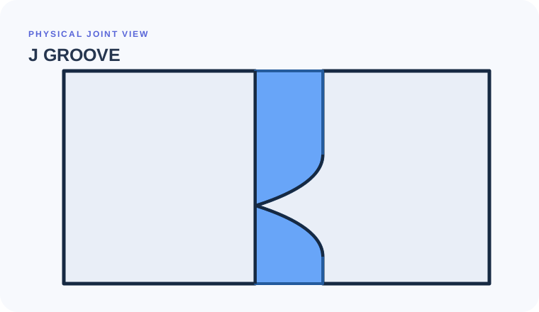
Mirrored curves that turn a J into another joint
Preparing both edges
Curving both mating edges creates a U groove rather than the specified J groove.
Mirroring by page position
Do not select the member based on the way the printed J faces; use the arrow convention.
Treating depth as weld size
Preparation depth and groove weld size are separate requirements when both are shown.
Does the machining note protect the square mating edge?
Use the full list before fabrication, fit-up, or inspection. This is a drawing-reading handoff—not a substitute for the governing acceptance standard.
- 01Identify the prepared member
- 02Find profile radius
- 03Read depth/root face
- 04Read opening and side
- 05Confirm machining and WPS
Evidence and limits for this J Groove lesson
This guide teaches common AWS-style drawing interpretation. It is educational material, not a substitute for the purchased standard, project specification, code, WPS, or qualified engineering direction.
How this page was made. The training diagrams, worked example, comparisons, and questions are original educational material. Read the editorial and technical review policy for the full process.
Save your place after J Groove.
This marker records reading progress only; it does not mean the topic is mastered. Use the six-question practice page to check your understanding.
Build outward from J Groove
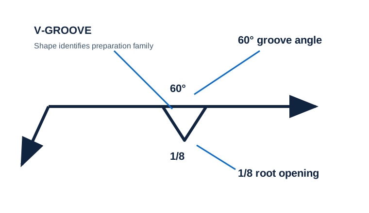 Groove Welds Overview
 U Groove
 Bevel Groove
 Arrow Side vs Other Side
Educational practice only. Verify production work against the governing drawing, applicable standard, WPS, and qualified instruction.