V-Groove Weld Symbol
A V-groove weld uses prepared edges on both members to form a V-shaped groove. The callout can specify depth of groove, groove weld size, included groove angle, and root opening.
- Recognize a V-groove preparation
- Separate included groove angle from individual bevel angles
- Read root opening and depth without assuming full penetration
Half-angle assumption
The included angle affects access, weld volume, heat input, and fit-up. A small angle-reading error can change preparation and filler-metal demand across an entire joint.
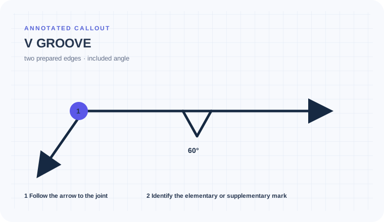
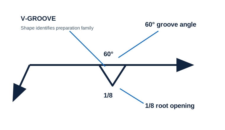
The callout shows V, 60°, and 1/8
Both mating members appear prepared, but the detail does not show equal bevels.
Read 60° as the included groove angle and 1/8 as the illustrated root opening. Confirm each member’s preparation and any depth or penetration requirement in the joint detail.
You do not automatically machine two 30° bevels when the detail assigns the included angle differently.
Assign angle, opening, and depth to the right geometry
Begin with the cue in the first column. The final column records the drawing, detail, procedure, or acceptance question that this callout cannot answer by itself.
| Visual cue | What it establishes | What still needs verification |
|---|---|---|
| V elementary symbol | V-groove family | Confirm single versus double-V from side placement and the joint detail. |
| 60° | Included groove angle in this example | Do not divide it equally unless the detail supports equal bevels. |
| 1/8 inside the V | Root opening in this example | Root opening does not prove root penetration. |
V and bevel grooves differ in prepared-member count
V groove
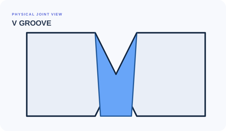
Both faces form the V-shaped groove
Evidence to useConfirm how each member is prepared.Bevel groove
One member is prepared against an unprepared mate
Evidence to useUse the broken-arrow/detail convention where applicable.Double V
Preparation and welding occur from both sides
Evidence to useLook for groove symbols on both sides of the reference line.Do not divide the angle until the section proves symmetry.
A plate splice shows a V-groove with a 60-degree included angle and a root-opening value. The individual bevels are only equal if the detail makes them equal.
Read the degree value as the included groove angle where shown.
Do not assume two 30-degree bevels without a symmetric detail.
Keep root opening separate from groove depth and effective throat.
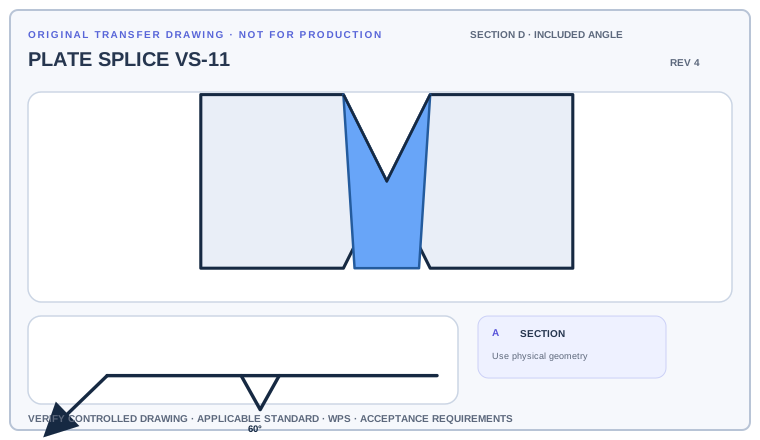
Mark the included angle, both prepared faces, root opening, and any depth or size value. Then state whether each bevel angle can be released from the evidence shown.
Deliverable · An annotated section that distinguishes included angle from member bevel anglesCompare with the field read +
The callout establishes a V-groove with the shown included angle and root opening. Individual member preparation, depth, and acceptance must agree with the controlled section and WPS.
From the V mark to two prepared members
Read the V shape as the preparation family, then separate the included angle from the root opening and any depth or size values shown to the left.
- Locate the V-groove symbol and applicable side.
- Read depth of groove and groove weld size to the left when shown.
- Read the included angle above or within the callout convention.
- Read root opening inside the V and verify the joint detail.
Half-angle and root-gap errors that change machining
Half-angle assumption
A 60-degree groove angle is the included angle; the individual bevels are not automatically 30 degrees unless the detail is symmetric.
Root opening as depth
The value inside the V describes separation at the root, not depth of groove.
Missing double preparation
A double-V uses symbols on both sides and must not be read as a single-V without inspecting placement.
Can both plate edges be prepared from this section?
Use the full list before fabrication, fit-up, or inspection. This is a drawing-reading handoff—not a substitute for the governing acceptance standard.
- 01Identify single or double V
- 02Read included angle
- 03Read root opening
- 04Find preparation depth
- 05Confirm penetration/backing and WPS
Evidence and limits for this V Groove lesson
This guide teaches common AWS-style drawing interpretation. It is educational material, not a substitute for the purchased standard, project specification, code, WPS, or qualified engineering direction.
How this page was made. The training diagrams, worked example, comparisons, and questions are original educational material. Read the editorial and technical review policy for the full process.
Save your place after V Groove.
This marker records reading progress only; it does not mean the topic is mastered. Use the six-question practice page to check your understanding.
Build outward from V Groove
 Groove Welds Overview
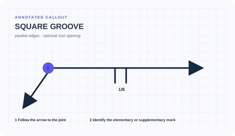 Square Groove
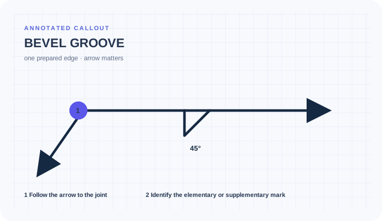 Bevel Groove
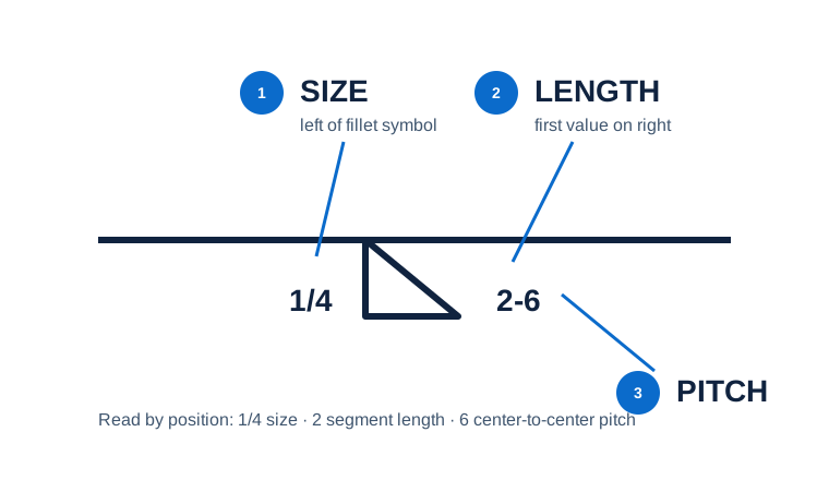 Size, Length & Pitch
Educational practice only. Verify production work against the governing drawing, applicable standard, WPS, and qualified instruction.