Multiple Reference-Line Welding Symbols
Multiple reference lines separate sequential operations tied to one arrowed joint. AWS A2.4:2020 also permits multiple subreference lines for certain groove-weld transitions around a joint.
- Keep operations on separate reference lines
- Trace all lines back to the common arrowed joint
- Confirm sequence without borrowing symbols or dimensions
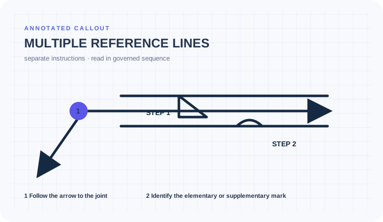
Merging all lines into one instruction
Multiple reference lines organize stages or changing requirements. If their content is merged, a preparation dimension can become a weld size, a finish can be applied too early, or a later operation can be skipped entirely.
One joint has preparation, welding, and finishing stages
Stacked reference lines point to the same transition joint; each line carries different information.
Trace the common arrow first, read the reference line closest to the arrow junction first, decode each later line separately, and keep every value and modifier on its own line. Confirm transition details and WPS requirements before release.
Preparation, deposition, and finishing occur in the intended sequence without values migrating from one line to another.
Keep every operation on its own reference line.
A repair callout uses multiple reference lines to organize preparation, welding, and a later operation on one joint. Values must not migrate between lines.
Begin with the reference line closest to the arrow junction under the convention used here.
Carry symbols, values, and modifiers only within their own line.
Confirm subreference-line or sequencing use against the applicable drawing convention and notes.
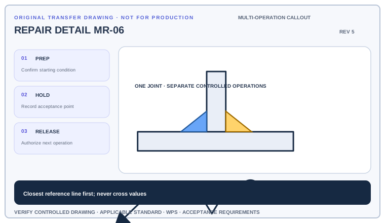
Number the operations beginning with the reference line closest to the arrow junction, copy each line into a separate traveler step, and identify the document that confirms the sequence.
Deliverable · A line-by-line operation traveler with no crossed dimensions or modifiersCompare with the field read +
Read the closest reference line first, then move outward one controlled operation at a time. All lines remain attached to the arrowed joint, but their values and modifiers do not combine unless the drawing explicitly says so.
Turn stacked lines into a controlled operation traveler
Trace the arrow to the joint, then begin with the reference line closest to the arrow junction and keep each line's information together. Information on one reference line must not be blended with another; each line carries its own operation, dimensions, and modifiers.
- Trace the arrow to the joint, then begin with the reference line closest to the arrow junction and keep each line's information together.
- Information on one reference line must not be blended with another; each line carries its own operation, dimensions, and modifiers.
- Multiple reference lines separate instructions or sequence; symbols above and below one line communicate side significance.
- Verify line order, operation sequence, joint transitions, tail notes, detail references, and whether multiple arrows are required.
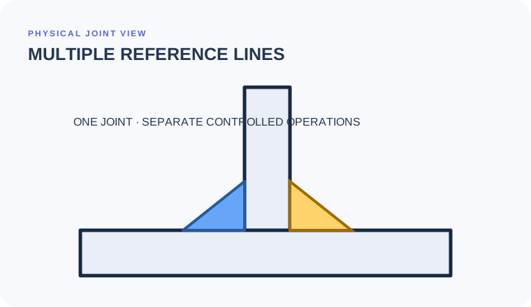
Read one reference line at a time
Begin with the cue in the first column. The final column records the drawing, detail, procedure, or acceptance question that this callout cannot answer by itself.
| Visual cue | What it establishes | What still needs verification |
|---|---|---|
| Common arrow | Identifies the physical joint shared by the stacked instructions | Confirm whether any line redirects to another detail or joint. |
| Each reference line | Carries an independent operation or stage | Keep its weld symbol, dimensions, modifiers, and tail information together. |
| Distance from arrow junction | Closest reference line is the first operation; farther lines follow in sequence | Do not substitute top-to-bottom page order, and still confirm notes, detail references, and WPS. |
| Transition detail | Explains where joint type or operation changes | Do not extend one line's requirement through a different joint condition. |
Values and modifiers that leak across lines
Merging all lines into one instruction
Each reference line carries its own symbol, dimensions, and modifiers. Combining them can assign values to the wrong operation.
Skipping sequence
Stacked lines may organize preparation, welding, and finishing in order. Confirm the applicable line-order convention and supporting notes.
Losing the common joint
The operations remain tied to the joint identified by the arrow unless the drawing explicitly redirects them.
Multiple lines organize sequence; they do not create multiple joints
Multiple reference lines
Separate stages tied to one arrowed joint
Evidence to useWhat distinct job belongs to each line?Symbols above and below one line
Side significance on a single instruction line
Evidence to useAre you looking at side placement rather than sequence?Multiple arrows
One instruction may apply to several locations
Evidence to useAre there several physical joints rather than several stages?Can the crew execute every line without combining instructions?
Use the full list before fabrication, fit-up, or inspection. This is a drawing-reading handoff—not a substitute for the governing acceptance standard.
- 01Trace the common arrow to the joint
- 02Decode each line independently
- 03Keep dimensions and modifiers with their line
- 04Confirm operation order and transitions
- 05Verify notes, detail references, inspection points, and WPS
Evidence and limits for this Multiple Reference Lines lesson
This guide teaches common AWS-style drawing interpretation. It is educational material, not a substitute for the purchased standard, project specification, code, WPS, or qualified engineering direction.
How this page was made. The training diagrams, worked example, comparisons, and questions are original educational material. Read the editorial and technical review policy for the full process.
Save your place after Multiple Reference Lines.
This marker records reading progress only; it does not mean the topic is mastered. Use the six-question practice page to check your understanding.
Build outward from Multiple Reference Lines
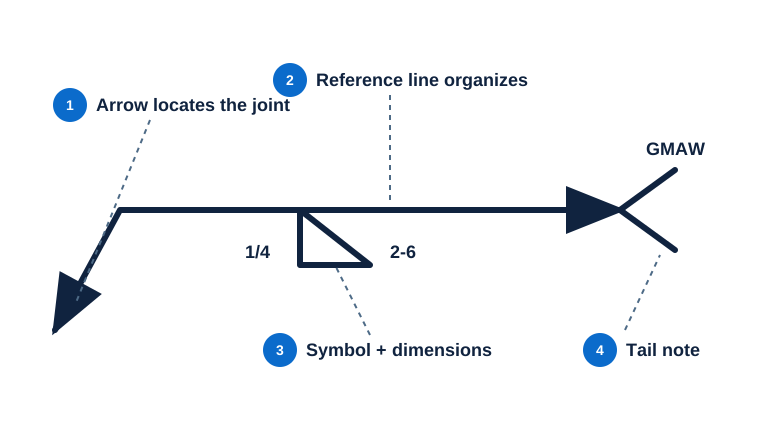 Symbol Anatomy
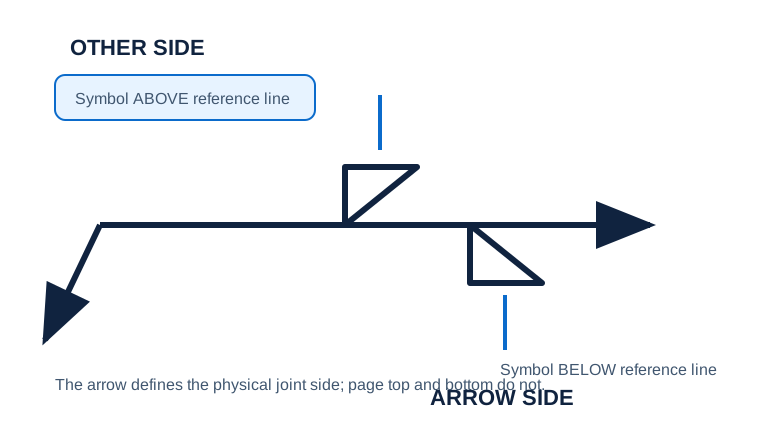 Arrow Side vs Other Side
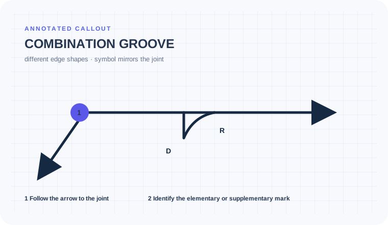 Combination Groove
Educational practice only. Verify production work against the governing drawing, applicable standard, WPS, and qualified instruction.