Projection Weld Symbol
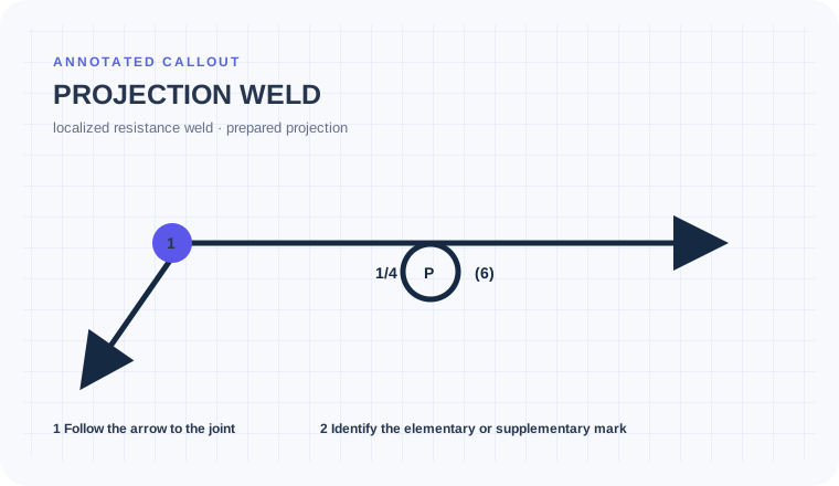
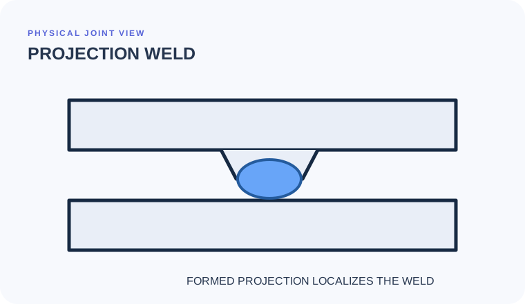
A projection weld is a resistance weld localized by a prepared projection or embossment on one of the members.
- Identify the formed projection that localizes a resistance weld
- Separate weld size, count, pitch, and strength information
- Verify projection geometry and electrode access before production
Treating it like a plug weld
Projection welds can resemble spot or plug instructions on a simplified print, but the part must contain a formed feature that localizes current and force. Missing that physical evidence changes tooling, process setup, and joint preparation.
Six embossed projections attach a bracket to sheet
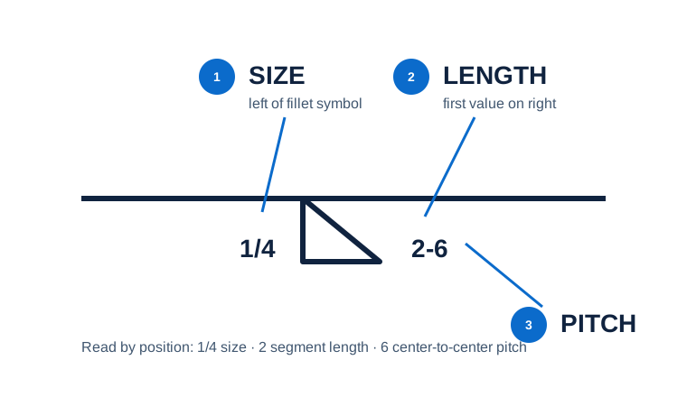
The callout shows 1/4 to the left, (6), and 2-unit pitch, while the bracket detail shows six formed dimples.
Confirm the formed projections first, then read 1/4 as size, (6) as quantity, and 2 as center-to-center pitch. Use a note or tail for any required strength and process information.
The layout is released as six sized projection welds at the stated pitch, with tooling, access, and acceptance verified instead of being converted into a six-hole plug-weld pattern.
Projection, spot, and plug use different physical features
Projection weld
Uses a formed projection or embossment
Evidence to useCan you point to the projection in the part detail?Spot weld
Joins members at a localized point without a prepared projection requirement
Evidence to useDoes the process rely on the member stack rather than an embossment?Plug weld
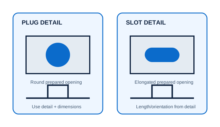
Deposits weld metal through a prepared opening
Evidence to useIs there an actual hole or slot to fill?Find the formed feature that localizes current and force.
A stamped bracket uses six formed projections against a cover sheet. The process plan must connect the callout to those physical features.
Confirm that a formed projection exists at every required weld location.
Keep left-side size separate from any strength requirement in the tail or note.
Do not substitute prepared plug openings for formed projections.
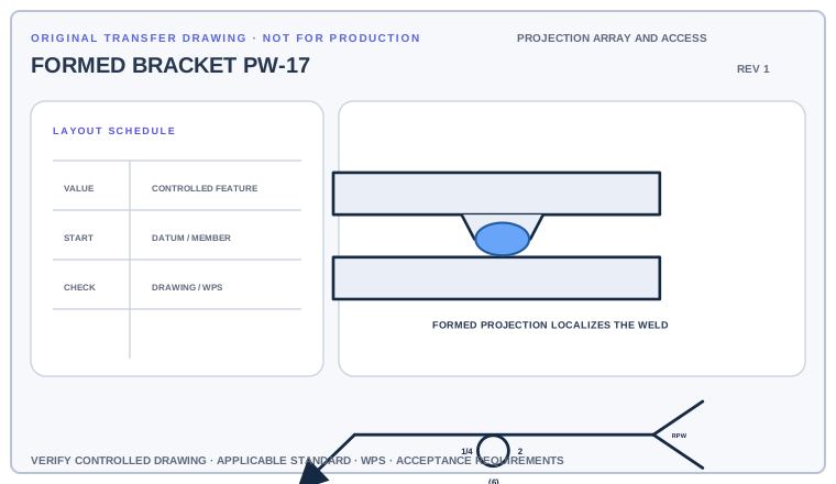
Number the six projections, check the stated pitch against the part layout, and list the geometry, electrode-access, and process details that the symbol does not provide.
Deliverable · A projection-weld setup checklist tied to the stamped featuresCompare with the field read +
The six formed projections define the localized resistance-weld locations at the stated pitch. Projection geometry, process setup, electrode access, and acceptance require the controlled detail and procedure.
Connect the circle callout to a formed projection
Begin with the cue in the first column. The final column records the drawing, detail, procedure, or acceptance question that this callout cannot answer by itself.
| Visual cue | What it establishes | What still needs verification |
|---|---|---|
| Formed projection in the detail | Physical feature used to localize resistance-welding current and force | Confirm shape, height, member stack-up, and which member carries it. |
| Value to the left | Projection-weld size under the current AWS convention | Do not substitute strength; put a required strength in a note or tail. |
| Parenthesized count and pitch | Number of welds and their center-to-center spacing | Locate the first/last weld and confirm the detail pattern. |
| Tail, note, and process detail | Carries strength or process information not encoded by the elementary symbol | Check electrode access, procedure qualification, and acceptance criteria. |
Translate number and pitch into a setup pattern
Inspect the joint detail to locate the projection and the members it brings into contact. Read weld size, number, and pitch in their applicable positions; use the tail or notes for process and strength information when required.
- Inspect the joint detail to locate the projection and the members it brings into contact.
- Read weld size, number, and pitch in their applicable positions; use the tail or notes for process and strength information when required.
- Projection welding uses a formed projection to localize current and force; a plug weld fills a prepared opening with weld metal.
- Verify projection geometry, member arrangement, process note, number, pitch, electrode access, and acceptance requirements.
When the process symbol is read without the stamped part
Treating it like a plug weld
A projection weld localizes resistance-welding current at a formed projection; a plug weld deposits metal into a prepared opening.
Swapping count and pitch
A parenthesized quantity and a spacing value do different jobs. Read each by its position before laying out the pattern.
Ignoring the formed feature
The symbol does not define projection height, shape, member thickness, electrode access, or process setup. Those requirements need the detail and procedure.
Are projection geometry and electrode access ready for setup?
Use the full list before fabrication, fit-up, or inspection. This is a drawing-reading handoff—not a substitute for the governing acceptance standard.
- 01Locate every formed projection
- 02Read weld size separately from count
- 03Read pitch and anchor the pattern
- 04Find strength/process information in notes or tail
- 05Verify tooling, electrode access, qualification, and acceptance
Evidence and limits for this Projection Weld lesson
This guide teaches common AWS-style drawing interpretation. It is educational material, not a substitute for the purchased standard, project specification, code, WPS, or qualified engineering direction.
How this page was made. The training diagrams, worked example, comparisons, and questions are original educational material. Read the editorial and technical review policy for the full process.
Save your place after Projection Weld.
This marker records reading progress only; it does not mean the topic is mastered. Use the six-question practice page to check your understanding.
Build outward from Projection Weld
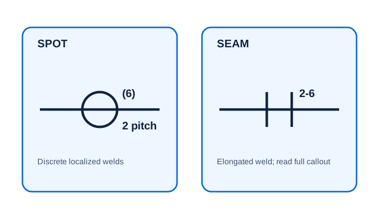 Spot & Seam Welds
 Plug & Slot Welds
 Size, Length & Pitch
Educational practice only. Verify production work against the governing drawing, applicable standard, WPS, and qualified instruction.