Plug and Slot Weld Symbols
Plug and slot welds join overlapping members by depositing weld metal in a hole or elongated slot in one member. The part detail establishes hole or slot geometry; the welding symbol adds size, fill, number, pitch, and related requirements.
- Distinguish a plug/slot weld from a spot weld
- Identify the prepared opening and the member containing it
- Read opening size, length, pitch, and fill requirements in context
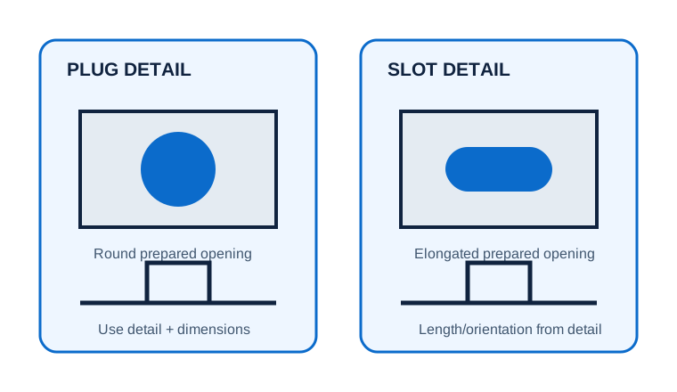
Wrong weld mechanism
Plug and slot welds require an actual opening in one member. Confusing them with spot welds changes joint preparation, access, and deposited weld metal.
A lap joint needs load transfer through the overlap
The drawing shows a rectangular plug/slot elementary symbol and a detail with holes in the top plate.
Confirm whether the opening is round or elongated, which member receives it, its dimensions and spacing, and whether the opening is completely or partially filled.
The shop prepares the intended openings instead of attempting a no-hole spot-welding operation.
Decide what must be cut before deciding what must be welded.
A reinforcement plate contains round openings in one zone and elongated openings in another. The welding symbol cannot replace the opening plan.
Retain the diameter mark with the plug dimension even though the basic symbol is plain.
Use the part detail to orient a slot; the elementary symbol does not rotate the opening for you.
Do not substitute a spot-weld process where the drawing requires prepared openings.
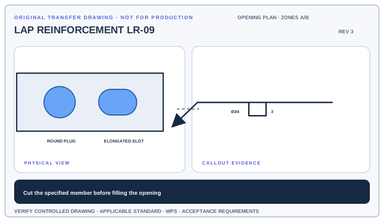
Prepare an opening schedule that identifies plug or slot, the member receiving the opening, diameter or width/length, pitch, orientation, and depth of fill.
Deliverable · A shop opening schedule tied to the correct overlapping memberCompare with the field read +
Round openings receive plug welds and elongated openings receive slot welds. Their geometry, layout, edge distance, and fill requirements come from the complete drawing and must be settled before cutting the top member.
Plug, slot, and spot create different work
Plug weld
Weld metal deposited through a generally round opening
Evidence to useIs a hole prepared in one overlapping member?Slot weld
Uses an elongated opening
Evidence to useRead slot length and orientation from the detail.Spot weld
Localized weld without a plug/slot opening
Evidence to useDo not order hole preparation unless the drawing requires it.Read the opening before the deposited metal
Begin with the cue in the first column. The final column records the drawing, detail, procedure, or acceptance question that this callout cannot answer by itself.
| Visual cue | What it establishes | What still needs verification |
|---|---|---|
| Rectangular elementary symbol | Plug or slot weld family | Use dimensions and the joint detail to distinguish round plugs from elongated slots. |
| Opening dimension | Controls hole diameter or slot width/length as placed | Do not treat it as fillet leg size. |
| Depth-of-fill information | Controls how much of the opening is filled where specified | Complete fill must not be assumed from appearance alone. |
| Pitch or count | Controls repetition of openings/welds | Confirm layout on the detail view. |
Move from symbol to cutting and fill requirements
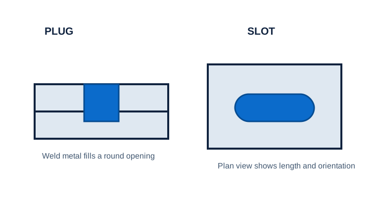
Confirm from the joint detail whether the opening is round or elongated. Then read diameter or width, depth of filling, number, pitch, slot length, and orientation in their specified locations.
- Inspect the part detail for a round hole or elongated slot.
- Read diameter or width on the left of the symbol as applicable.
- Read fill depth inside the symbol and number or pitch where specified.
- For slots, find length and orientation in the drawing information.
How a symbol mix-up becomes a wrong part
Wrong weld mechanism
A plug weld fills an opening to fuse overlapping members; it is not merely a circular fillet around the opening edge.
Fill versus thickness
Depth of filling is a weld requirement. Material thickness is a separate part dimension unless the drawing equates them.
Ignoring the detail view
Slot orientation and layout often cannot be communicated by the elementary mark alone.
Can the opening plan be released without guessing?
Use the full list before fabrication, fit-up, or inspection. This is a drawing-reading handoff—not a substitute for the governing acceptance standard.
- 01Identify plug or slot
- 02Locate the member with the opening
- 03Read opening dimensions
- 04Read fill depth and spacing
- 05Check the detail for orientation and edge distance
Evidence and limits for this Plug & Slot Welds lesson
This guide teaches common AWS-style drawing interpretation. It is educational material, not a substitute for the purchased standard, project specification, code, WPS, or qualified engineering direction.
How this page was made. The training diagrams, worked example, comparisons, and questions are original educational material. Read the editorial and technical review policy for the full process.
Save your place after Plug & Slot Welds.
This marker records reading progress only; it does not mean the topic is mastered. Use the six-question practice page to check your understanding.
Build outward from Plug & Slot Welds
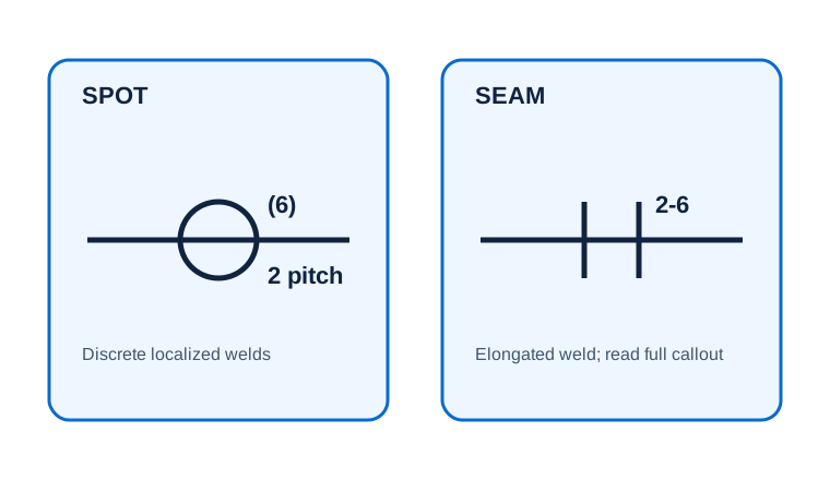 Spot & Seam Welds
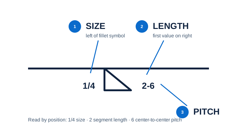 Size, Length & Pitch
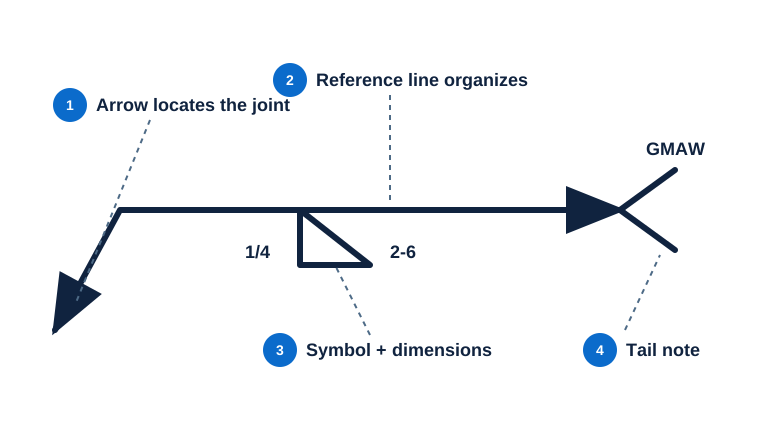 Symbol Anatomy
Educational practice only. Verify production work against the governing drawing, applicable standard, WPS, and qualified instruction.