Stud Weld Symbol
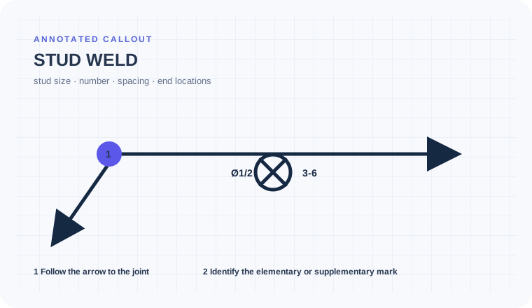
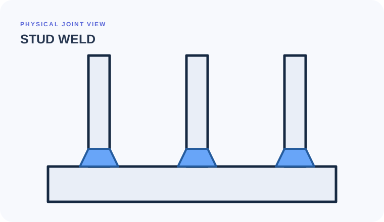
A stud-weld callout specifies studs welded directly to the surface of a member at defined locations.
- Identify the face that receives welded studs
- Read stud size, quantity, pitch, and end locations as separate controls
- Recognize when a stud layout is incomplete
Losing the first and last location
A correct stud count can still produce a rejected layout if the row is anchored from the wrong datum or installed on the wrong face. Stud identity, base material, access, and qualified setup matter as much as spacing.
A count and pitch still need end locations.
A deck plate receives three studs at six-unit pitch, but a datum is needed to locate the first stud and verify the last.
Keep stud quantity separate from stud diameter.
Measure pitch between centers, not from the edge of one stud to the next.
Do not invent a start location from the symbol alone.
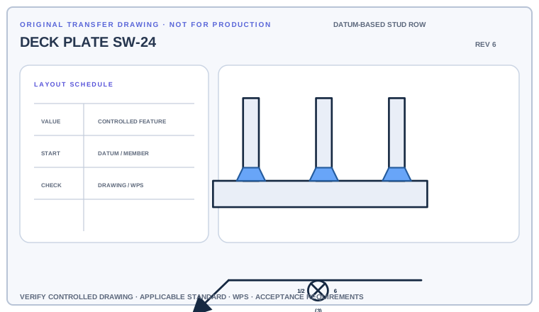
Set out the row from datum A, mark all stud centers, calculate the last center location, and list stud designation and process data still required.
Deliverable · A datum-based stud layout with first and last centers checkedCompare with the field read +
Place the stated number of studs at the specified center-to-center pitch from the drawing datum. Confirm stud designation, material, process, ferrule or shielding needs, access, and qualification separately.
Eight shear studs run along the top flange
The symbol gives 3/8 size, (8), and 4-unit pitch, but the first stud is located by a separate detail dimension from the plate edge.
Identify the top flange as the receiving face, read the size, quantity, and pitch, then use the detail datum to locate the first and last stud.
The row has the correct count and spacing without drifting off the designed start location, and the stud designation and qualified process are confirmed before installation.
Read size, count, and pitch without losing the datum
Begin with the cue in the first column. The final column records the drawing, detail, procedure, or acceptance question that this callout cannot answer by itself.
| Visual cue | What it establishes | What still needs verification |
|---|---|---|
| Arrowed member face | Surface that receives the stud welds | Check access, coating, curvature, and base material. |
| Stud size | Required stud dimension in the applicable callout | Confirm complete stud designation, length, material, and end condition. |
| Count and pitch | Number of studs and center-to-center repetition | Do not assume they locate the first or last stud. |
| Datum/detail dimensions | Anchor the stud row to the part | Check accumulated spacing against available length and edge clearances. |
Set out the entire stud row
Locate the stud positions and identify which face of the member receives them. Read stud size, number, spacing, and the location of the first and last stud from the complete drawing.
- Locate the stud positions and identify which face of the member receives them.
- Read stud size, number, spacing, and the location of the first and last stud from the complete drawing.
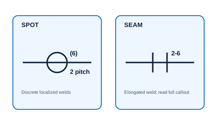
- A stud weld attaches a stud end to a surface; a spot weld joins overlapping members at localized points.
- Verify stud designation, base material, number, pitch, end locations, process, access, and qualification requirements.
Stud welds attach a separate stud; spot welds join sheets
Stud weld
Attaches a separate stud end to a surface
Evidence to useIs a stud component identified?Spot weld
Directly joins overlapping members at localized points
Evidence to useAre there two sheet members rather than a stud?Plug weld
Fills a prepared opening in one member
Evidence to useDoes the detail require a hole or slot?Layouts that have correct spacing but the wrong start
Losing the first and last location
Count and pitch do not anchor a row by themselves. The drawing must locate the end studs or provide an overall layout.
Reading it as a spot weld
A stud weld attaches the end of a separate stud to a surface; a spot weld joins overlapping members at a localized point.
Skipping the stud designation
Diameter alone does not define stud material, length, end condition, ferrule, or qualified installation procedure.
Can the first and last stud be inspected from the drawing?
Use the full list before fabrication, fit-up, or inspection. This is a drawing-reading handoff—not a substitute for the governing acceptance standard.
- 01Identify the receiving face
- 02Confirm stud designation and size
- 03Read quantity and pitch
- 04Anchor first and last stud from drawing datums
- 05Verify base material, access, process, and qualification
Evidence and limits for this Stud Weld lesson
This guide teaches common AWS-style drawing interpretation. It is educational material, not a substitute for the purchased standard, project specification, code, WPS, or qualified engineering direction.
How this page was made. The training diagrams, worked example, comparisons, and questions are original educational material. Read the editorial and technical review policy for the full process.
Save your place after Stud Weld.
This marker records reading progress only; it does not mean the topic is mastered. Use the six-question practice page to check your understanding.
Build outward from Stud Weld
 Spot & Seam Welds
 Projection Weld
 Size, Length & Pitch
Educational practice only. Verify production work against the governing drawing, applicable standard, WPS, and qualified instruction.