Surfacing Weld Symbol
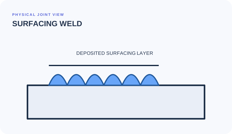
A surfacing weld deposits weld metal on a surface to build thickness, restore dimensions, or provide selected properties.
- Recognize surfacing as deposited material on an area rather than a joint weld
- Separate deposited thickness from finished dimension
- Find boundaries, layer orientation, and machining allowance
Turning surfacing into a joint weld
Surfacing controls material buildup over an area. If the reader treats the size as a finished dimension or assumes the entire part is covered, material use, machining stock, distortion, and final geometry can all be wrong.
A worn shaft journal needs buildup before machining
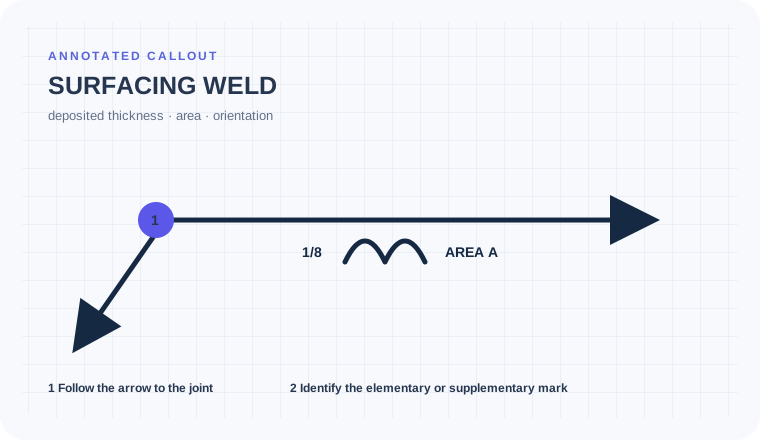
The callout specifies 1/8 surfacing over AREA A in two layers; a separate dimension defines the final machined diameter.
Use AREA A to establish extent, read 1/8 as deposited surfacing thickness, follow the two-layer orientation, and keep the final machined dimension separate.
Enough compatible material is deposited for restoration without coating unrelated surfaces or machining below the required finished size.
Deposit enough stock for the finished dimension—not an undefined blanket.
A worn shaft has one controlled build-up zone, a deposited thickness requirement, and a separate machining target.
Treat surfacing as deposition on a surface, not a joint weld between members.
Keep deposited thickness separate from the finished machined dimension.
Confirm material, layers, overlap, orientation, and termination in the procedure.
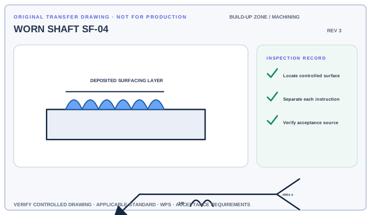
Shade the deposit boundary, distinguish deposited from finished thickness, and prepare a layer-orientation note that leaves machining allowance explicit.
Deliverable · A build-up and machining handoff for one defined shaft zoneCompare with the field read +
Deposit surfacing only within the defined zone to the stated buildup, using the controlled layer direction and material. Preserve the specified machining allowance for the final dimension.
Assign thickness, area, and layer direction separately
Begin with the cue in the first column. The final column records the drawing, detail, procedure, or acceptance question that this callout cannot answer by itself.
| Visual cue | What it establishes | What still needs verification |
|---|---|---|
| Surfacing symbol | Deposited weld metal builds, restores, or changes a surface | Do not infer a joint between separate members. |
| Size value | Specified surfacing thickness | Separate deposited buildup from the finished dimension after machining. |
| Area boundary or detail | Location and extent of the deposit | Check terminations, excluded areas, and transition requirements. |
| Layer/orientation note | Controls sequence, number of layers, or bead direction | Confirm compatible material, procedure, dilution control, and machining allowance. |
Coordinate deposition with the machining handoff
Identify the exact surface area and the purpose of the deposited layer before reading dimensions. The size value controls deposited thickness, while the drawing or detail must define area, extent, and orientation.
- Identify the exact surface area and the purpose of the deposited layer before reading dimensions.
- The size value controls deposited thickness, while the drawing or detail must define area, extent, and orientation.
- Surfacing builds or restores a surface; it is not automatically a joint weld between separate members.
- Verify material, layer thickness, area boundaries, orientation, number of layers, machining allowance, and procedure.
Build-up notes that confuse deposited and finished size
Turning surfacing into a joint weld
Surfacing deposits material onto a defined area; it does not automatically join two separate members.
Confusing deposited and finished thickness
If machining follows, the deposited buildup and final dimension may differ. Read both the surfacing requirement and machining note.
Missing area and layer direction
Thickness alone does not define boundaries, bead orientation, number of layers, overlap, or termination.
Surfacing adds stock; a joint weld joins members
Surfacing
Deposits material over a defined surface area
Evidence to useWhere are the area boundaries?Joint weld
Joins separate members at a joint
Evidence to useIs a second member actually being connected?Finish machining
Removes buildup to a final dimension
Evidence to useWhat stock must remain before and after machining?Are area boundaries and machining allowance both explicit?
Use the full list before fabrication, fit-up, or inspection. This is a drawing-reading handoff—not a substitute for the governing acceptance standard.
- 01Identify the target surface and purpose
- 02Read deposited thickness
- 03Locate exact area boundaries
- 04Read layers, orientation, and material notes
- 05Verify procedure, machining allowance, and final dimension
Evidence and limits for this Surfacing Weld lesson
This guide teaches common AWS-style drawing interpretation. It is educational material, not a substitute for the purchased standard, project specification, code, WPS, or qualified engineering direction.
How this page was made. The training diagrams, worked example, comparisons, and questions are original educational material. Read the editorial and technical review policy for the full process.
Save your place after Surfacing Weld.
This marker records reading progress only; it does not mean the topic is mastered. Use the six-question practice page to check your understanding.
Build outward from Surfacing Weld
 Edge Weld
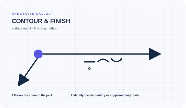 Contour & Finish
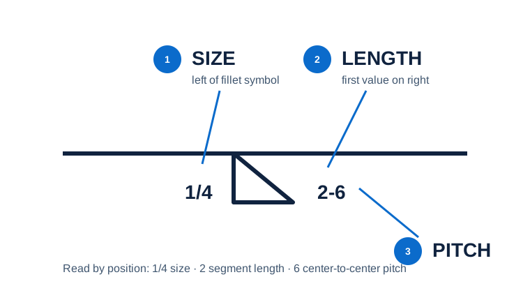 Size, Length & Pitch
Educational practice only. Verify production work against the governing drawing, applicable standard, WPS, and qualified instruction.