Weld-All-Around Symbol
The weld-all-around circle indicates that the specified weld continues around the complete applicable joint. It does not mean weld every edge of the part, and it does not identify the weld type by itself.
- Recognize the all-around circle at the arrow/reference junction
- Trace the complete applicable joint boundary
- Avoid treating all-around as ‘weld every edge on the part’
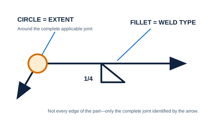
Every edge versus one joint
Extent is a geometry decision. Applying an all-around instruction to the wrong boundary can add unnecessary weld, distortion, time, and inaccessible work.
Trace the applicable joint boundary without welding every visible edge.
A rectangular tube meets a base plate beside unrelated plate edges and an access opening. The all-around circle follows the arrowed joint only.
Start at the joint touched by the arrow, not at the outer silhouette of the part.
Follow continuity around that joint and stop where the joint itself stops.
Keep the circle as an extent modifier; it does not name the weld family.
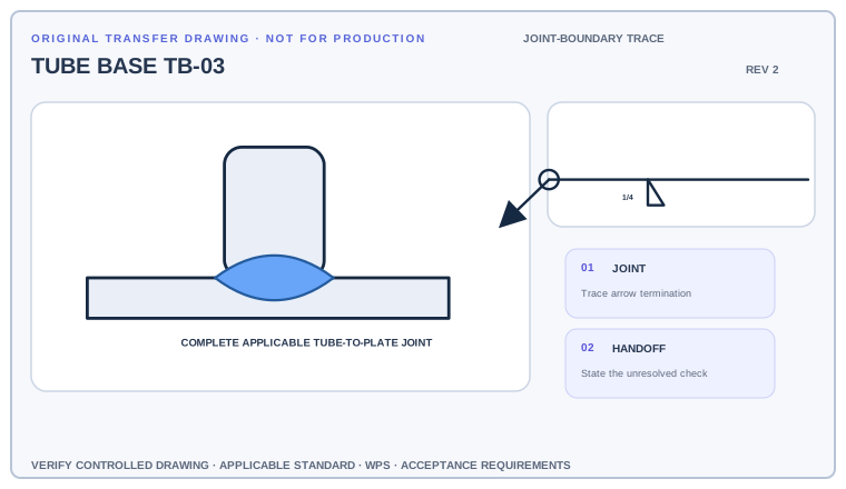
Trace the continuous boundary governed by the circle, cross out two nearby edges that are not included, and identify the elementary weld symbol that still controls weld type.
Deliverable · A boundary markup showing exactly where the all-around instruction starts and closesCompare with the field read +
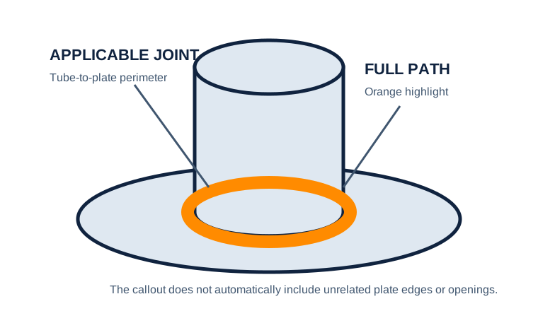
The circle extends the indicated weld around the complete tube-to-base joint. It does not apply to the access opening, the plate perimeter, or unrelated edges visible in the view.
A fillet callout points to a rectangular attachment
A circle appears at the arrow/reference junction, but the part has several unrelated edges.
Trace the joint continuously connected to the arrow location and determine which perimeter the callout governs. Use views and details to resolve interrupted or inaccessible boundaries.
Only the intended attachment joint is welded around—not every visible edge of the component.
Let the arrow choose the joint and the circle choose its extent
Begin with the cue in the first column. The final column records the drawing, detail, procedure, or acceptance question that this callout cannot answer by itself.
| Visual cue | What it establishes | What still needs verification |
|---|---|---|
| Circle at the arrow/reference junction | Weld extends around the complete applicable joint | Position distinguishes it from a centered spot-weld circle. |
| Arrow location | Anchors the joint whose boundary must be traced | Do not jump to a separate joint or edge. |
| Base weld symbol | Names the weld placed around that joint | The circle changes extent, not weld type. |
Walk the joint boundary before estimating length
Find the circle at the arrow/reference-line junction, identify the exact joint touched by the arrow, then read the elementary weld symbol and dimensions that the circle modifies.
- Find the circle at the arrow/reference-line junction.
- Locate the exact joint at the arrow tip.
- Trace the applicable joint around its complete perimeter.
- Read the weld type, side, size, and any notes that apply along that path.
All-around and field marks answer different questions
All around
Continuous extent around the applicable joint
Evidence to useCan the boundary be followed continuously from the arrowed joint?All over / general note
May apply more broadly by a different instruction
Evidence to useDo not enlarge an all-around circle into a part-wide requirement.Spot-weld circle
Centered elementary symbol for a localized weld
Evidence to useCheck the circle’s position on the reference system.Where an all-around circle is stretched too far
Every edge versus one joint
The circle applies to the arrowed joint, not automatically to every edge or opening on the component.
Modifier versus type
A fillet, groove, or other elementary symbol is still needed to state what weld continues around.
Ambiguous extent
Complex geometry may require multiple arrows, sections, or dimensions rather than a single all-around callout.
Does the traced path remain one continuous applicable joint?
Use the full list before fabrication, fit-up, or inspection. This is a drawing-reading handoff—not a substitute for the governing acceptance standard.
- 01Identify the arrowed joint
- 02Trace its complete boundary
- 03Check for breaks or inaccessible areas
- 04Read base weld size and side
- 05Verify views and details agree
Evidence and limits for this Weld All Around lesson
This guide teaches common AWS-style drawing interpretation. It is educational material, not a substitute for the purchased standard, project specification, code, WPS, or qualified engineering direction.
How this page was made. The training diagrams, worked example, comparisons, and questions are original educational material. Read the editorial and technical review policy for the full process.
Save your place after Weld All Around.
This marker records reading progress only; it does not mean the topic is mastered. Use the six-question practice page to check your understanding.
Build outward from Weld All Around
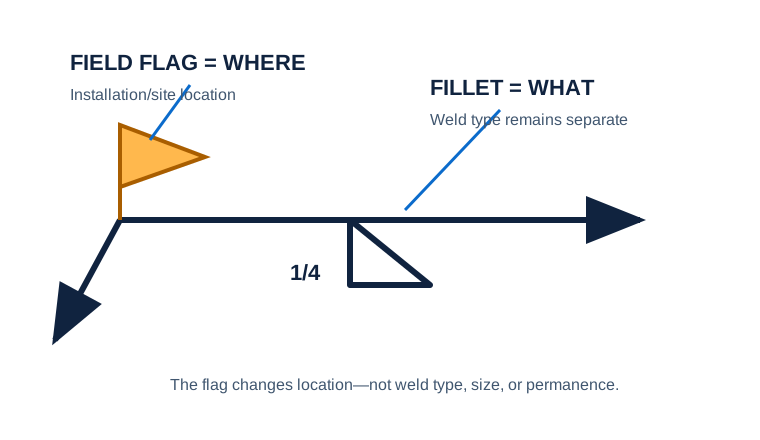 Field Weld
 Fillet Weld
 Symbol Anatomy
Educational practice only. Verify production work against the governing drawing, applicable standard, WPS, and qualified instruction.